Effective Use of MPI to Speed Solutions
Most Users can Skip this Post
This post addressed a problem that occurred with in FDS and PyroSim for versions 2019.1 through 2020.2. During that time period, if a model had more meshes than available processors and the user selected the default Run FDS Parallel option, the last processor would be assigned all excess meshes and solution times would be long.
This issue was addressed in PyroSim 2020.3, so most users can use the default Run FDS Parallel option with satisfactory solution times. This post does contain useful information for users who want additional background on MPI or who want to manually assign specific meshes to processes.
 How PyroSim Currently Runs MPI
By default, when the user clicks Run FDS Parallel in PyroSim, PyroSim compares the number of meshes with the number of logical processors. If the number of meshes is less than or equal to the number of logical processors, then a process is started for each mesh and the solution proceeds. This is often the best approach.
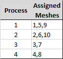
However, if the number of meshes is greater than the number of logical processors then PyroSim performs additional steps. By default, PyroSim will start the same number of processes as logical processors and will assign multiple meshes to each process. This is done in the order of the meshes, so if your model has 10 meshes and your computer has 4 logical processors, the meshes will be assigned as shown below. The mesh assignment can be seen in the MESH lines of the FDS input file. This will provide reasonable solution times.
To try other MPI options that are available when the number of meshes is greater than the number of logical processors, click Preferences on the File menu. Go to the FDS tab. The default option for Optimize Processor Utilization is Basic and the default option for Parallel Execution Settings is Limit Processes Based on Logical Processor Count.
If you select Create Process for Each Mesh, PyroSim will create as many processes as meshes. MPI will be launched with options that attempt to mimic the earlier "round-robin" behavior. However, the current implementation of the Intel MPI library does not perform this operation as efficiently as earlier, so solution times may more than double the times obtained using the default behavior.
If the user wants to assign meshes manually to processes, select the None option for Optimize Processor Utilization. Then use the cluster option as described below.
Background for this Post
The MPI parallel version of FDS can be used with multiple meshes to significantly reduce PyroSim/FDS solution times. Starting with PyroSim 2019.1 changes in the behavior of MPI multiprocess execution require users to manually assign meshes to processors when the number of meshes exceed the number of logical processors. This post will provide some background and examples of how to effectively use MPI to speed solutions.
Prior to PyroSim 2019.1, the user could simply click Run FDS Parallel and PyroSim would launch a process for each mesh. If the number of meshes (processes) exceeded the number of logical processors, the FDS MPI implementation would "round-robin" through all the processes, automatically balancing the processor load. FDS 6.7.1 that was included in PyroSim 2019.1 changed to a new FDS MPI implementation. Until PyroSim 2020.3 run times became significantly longer if more processes were started than the number of available logical processors. As a result, the maximum number of processes started by PyroSim was limited to the number of logical processors. This caused long run times if the user clicked Run FDS Parallel and the number of meshes exceeded the number of processors, since all additional meshes are assigned to the last processor.
In this post, we will focus on running MPI on a single Windows computer with a multicore processor. We will focus on a simple approach, but the user should recognize that there may be different options that could additionally speed the solution for your case.
In the following description, sentences in quotes are taken from the FDS User Guide. The FDS User Guide has a good background description on the use of multiple processors in Chapter 3, Running FDS.
Cores and Logical Processors
You will need to know the number of cores and logical processors of your computer. "For a typical Windows computer, there is one CPU per socket. Each CPU typically has multiple cores, and each core is essentially an independent processing unit that shares access to power and memory." Processors manufactured by Intel support a technology named Hyper Threading that doubles the number of apparent processors. These processors are called logical processors to distinguish them from the physical cores. To effectively run FDS, you must not launch more processes than the number of available logical processors. Be aware that depending on computer configuration, the number of logical cores may not be double the physical core count, even if the processor is capable of hyper threading.
To find the number of sockets, cores, and logical processors in Windows start Task Manager and click the Performance tab. The values for your computer will be displayed in the CPU section, as shown in Figure 1. (As an aside, to change the Task Manager graph from showing overall CPU utilization to individual processors, right-click on the graph, select Change graph to, and click Logical processors.)
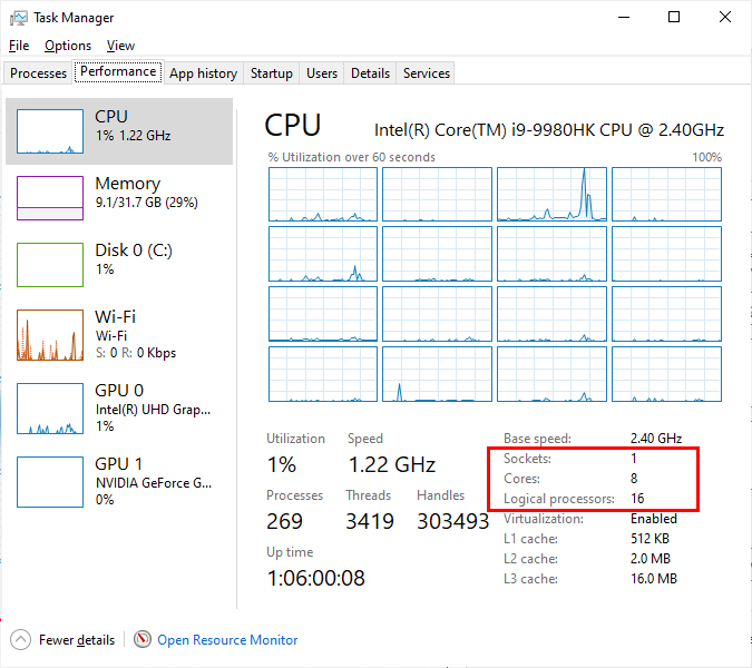
Note that the number of processors depends on your computer, while the number of processes is defined at run time and indicates how many of the available processors will be used during the solution.
Strategies for Using MPI
To use MPI for a parallel solution you must have multiple meshes. There can be many constraints that dictate how the meshes are arranged. If modeling a fire, meshes with smaller cells will typically be used for the fire and meshes with larger cells will be used away from the fire. Geometry, such long halls or atria can impose additional constraints. Accurate modeling of fans and HVAC flow may require a fine mesh resolution (see Two-dimensional benchmark test).
Within these constraints, we will describe two basic approaches that should result in near-optimal solution times. We will then provide examples of each.
Simplest Approach: The number of meshes is less than or equal to the number of logical processors
For the simplest approach, use the following guidelines:
- If possible, mesh the problem so that the number of meshes is equal to the number of cores on your computer. If that is not possible, you must keep the number of meshes less than or equal to the number of logical processors.
- All meshes should have approximately the same number of cells.
To run the simulation, on the Analysis menu click Run FDS Parallel. Now wait. Get a cup of coffee, or maybe eat dinner, or maybe go to bed and check progress tomorrow! See the hints on running long problems below.
Second Approach: The number of meshes exceeds the number of logical processors
If the number of meshes exceeds the number of available logical processors, each mesh must be manually assigned to a process by the user. The Run FDS Cluster option is then used for the solution.
At this time, assigning meshes to processes is a manual operation and is described in the post Assign FDS Meshes to Specific MPI Processes. Use the following guidelines:
Mesh the problem as required for your solution.
Decide how many processes you will use. A good place to start is to use the number of cores on your computer.
Assign meshes to each process.
Assign the meshes so that the total number of cells assigned to each process is approximately the same. Note that numbering of processes starts at zero, so eight processes will be numbered 0 through 7.
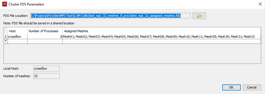
Run the simulation using the Run FDS Cluster option which will open the Cluster FDS Parameters dialog. Specify the number of processes. If you used eight processes when assigning the meshes in Step 3, specify 8 in this dialog.
To run the simulation, click OK in the Cluster FDS Parameters dialog. You might need to give your computer password. Separately you can follow these instructions to set the password for future use. See the hints on running long problems below.
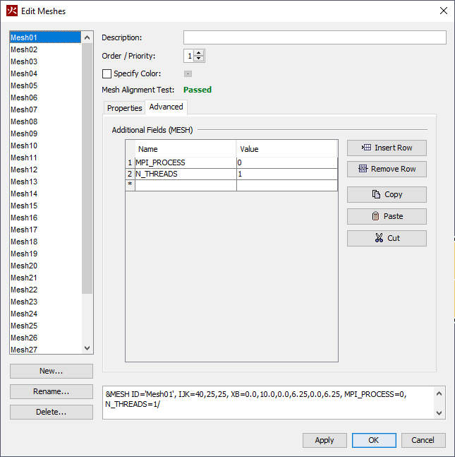
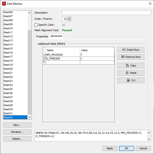
Step 3 is illustrated in Figure 2 and Figure 3 which show a simulation with 32 meshes using 8 processes. In this case, meshes 1 through 4 are assigned to MPI_PROCESS 0 (Figure 2), meshes 5 through 8 are assigned to MPI_PROCESS 1, continuing until mesh 32 is assigned to MPI_PROCESS 7 (Figure 3). The number of threads is specified as one (N_THREADS 1) for all meshes.
Step 4 is illustrated in Figure 4 which shows the Run FDS Cluster dialog and how to assign 8 processes.
How to Verify Processor Load Balance
"At the end of a calculation, FDS prints out a file called CHID_cpu.csv that records the amount of CPU time that each MPI process spends in the major routines.
For example, the column header VELO stands for all the subroutines related to computing the flow velocity; MASS stands for all the subroutines related to computing the species mass fractions and density."
Figure 5 shows a case where some meshes were not assigned to processes. As a result, the last process was assigned all remaining meshes. This makes the total run time longer as most processes must wait on the overloaded process as the simulation steps through time.
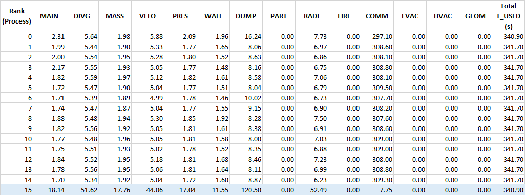
Figure 6 shows a case where the number of meshes and processes were the same, so the load is balanced.

Examples
Solution Speed Using MPI
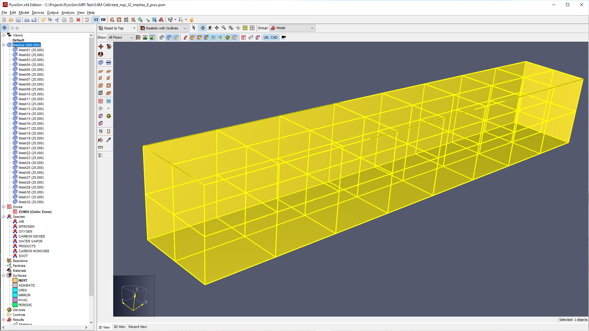
The model shown in Figure 7 was used to test the effect of using different numbers of meshes and MPI processes. The geometry remained the same, but cases were run with 1 to 32 meshes. Cases were run with 0.8M, 1.6M, and 6.4M total cells in the model. There was no specified flow or fire in the model. The top boundary was an OPEN surface.
Using more cells can rapidly increase the solution time. For example, if you have a model with 1M cells, reducing the size of the cells by 1/2 in the X, Y, and Z directions will give you 8M cells. In addition, the time step will be reduced by a factor of two. So, simply refining the mesh by a factor of two will result in approximately a factor of 16 increase in run time. This is why you only want to refine the mesh where necessary.
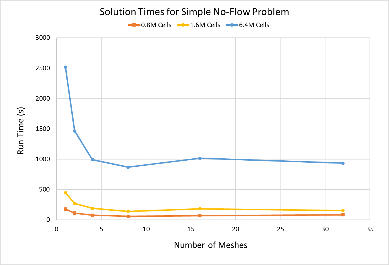
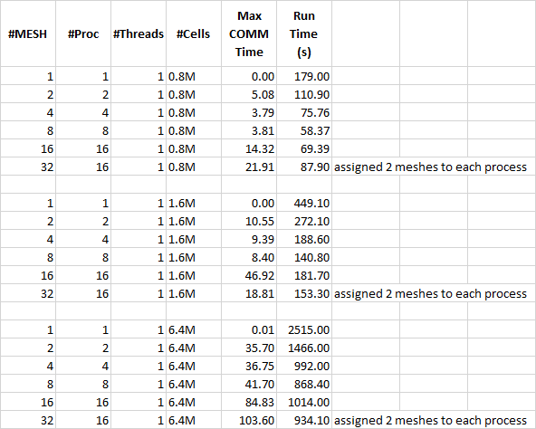
The solution times are shown in Figure 8. As noted, the computer had 8 cores with 16 logical processors. For meshes 1 through 16 the number of processors is the same as the number of meshes and the solution was simply run by clicking Run FDS Parallel. For the 32 mesh case, 2 meshes were assigned to each of the 16 processes and the solution used Run FDS Cluster.
The test computer has 8 cores. For the test problem, the shortest solution times are for the cases where the number of MPI processes matched the number of cores (8 meshes and 8 cores). It is not guaranteed that matching the number of MPI processes and cores will always result in the shortest times, but this provides guidance that should give reasonable results.
You can also see from the results that there are diminishing returns as you add additional meshes and associated processes. If you have a server computer which may have as many as 32 physical cores or more, you may use your compute resources by running multiple models or cases simultaneously. Since the speed gained by moving from 4 to 8 meshes or from 8 to 16 may not be significant, you may get more total work finished faster by running 4 simultaneous 4-mesh problems using the same 16 cores instead of running each case with 16 meshes in sequence.
A Few Variations
We will briefly discuss three variations for this test problem.
- The first case is 0.8 M cells, 16 meshes, and 8 processes with 2 threads for each process. This gave a run time of 66.12 seconds, slightly slower than the best time of 58.37 seconds.
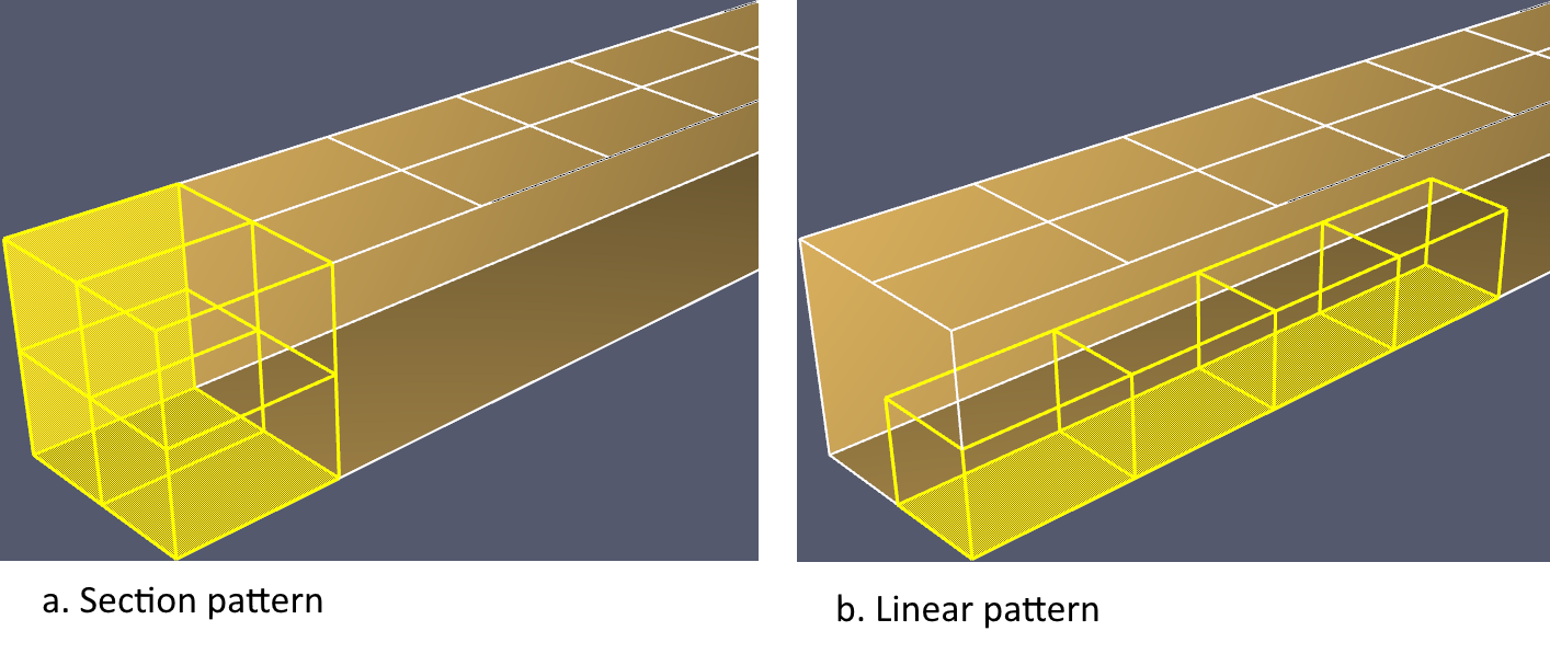
- The second case is 0.8 M cells, 32 meshes, and 8 processes with 4 meshes assigned to each process in a linear pattern (Figure 10). This gave a run time of 78.05 seconds, again slower than the best time of 58.37 seconds.
- The third case is 0.8 M cells, 32 meshes, and 8 processes with 4 meshes assigned to each process in a section pattern (Figure 10). This gave a run time of 80.04 seconds, slower than the best time of 58.37 seconds.
The apparent conclusion, at least for this test problem, is that matching cores and meshes gives the shortest time.
Fire Simulation
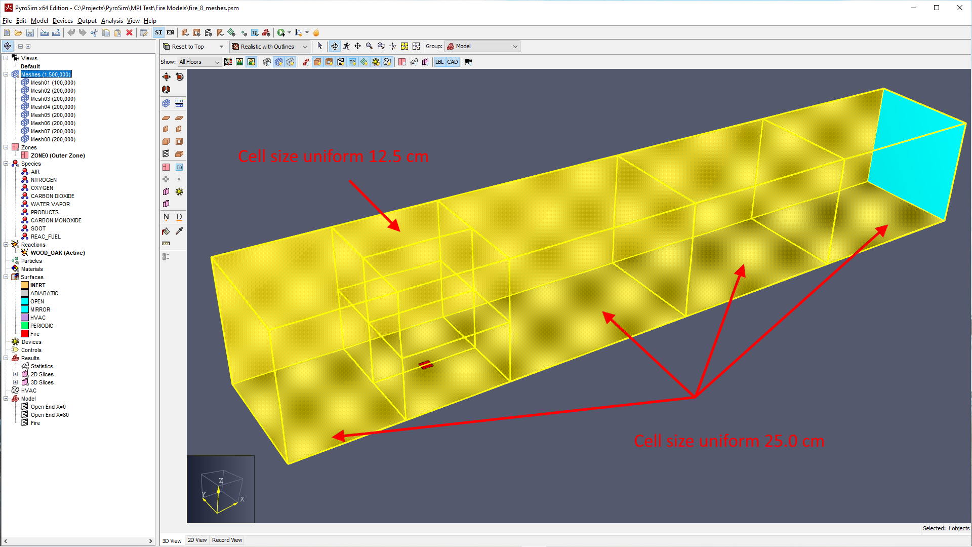
A simple fire simulation illustrates using refined cells near the fire and larger cells away from the fire. This model used 8 meshes. The fire had a heat release rate of 2 MW. For a 2 MW fire, D*/10 = 0.126536 m so the cell size of the meshes around the fire is 12.5 cm. Away from the fire a cell size of 25.0 cm is used. 1.5 M cells were used with all meshes having an equal number of 200,000 cells, except for Mesh01 that had 100,000.
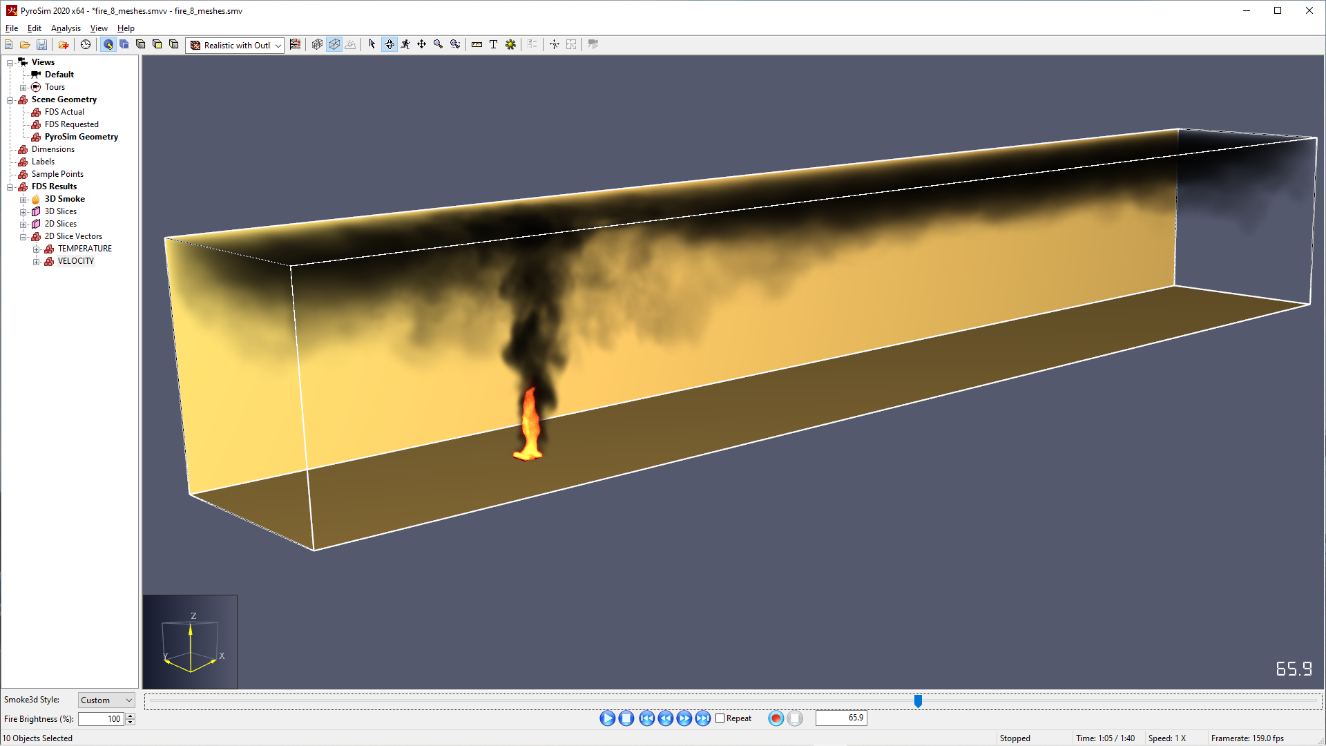
The solution was run for 100 seconds. A visual check of the results shows a smooth transition across the boundaries of meshes with small cells and larger cells.
Topics Not Addressed in this Post
OpenMP
"If your simulation involves only one mesh, you can exploit its multiple processors or cores using OpenMP." Figure 14 shows the default PyroSim OpenMP settings that use up to four OpenMP threads when running with one processor (Run FDS) and one OpenMP thread when running with multiple processors (Run FDS Parallel). We do not recommend that the user change these values.
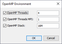
The FDS User Guide states "Because it more efficiently divides the computational work, MPI is the better choice for multiple mesh simulations. … It is usually better to divide the computational domain into more meshes and set the number of OpenMP threads to 1." This matches our experience.
For more information see the FDS User Guide.
Using Many Processors
This post applies to problems with a moderate number of meshes (less than 50). See the FDS User Guide for running thousands of meshes.
Running Long Problems
If a simulation is going to take more than one day, first make sure that you really need that resolution. Before starting the final analysis, run a short test case to make sure everything is correct.
It is useful to run a long problem by breaking it into segments, using restarts for each segment. While it is theoretically possible to run a long simulation saving restarts at intervals while continuing the solution, our experience favors running the solution for a time segment, stopping the solution at the end of that segment, and saving a restart at that time. This gives a reliable restart and the continuing solution will be correctly appended to the existing outputs. If your computer stops prematurely you can restart from the last saved location.
Here are the steps:
- Based on your short run, estimate the solution time that will be reached in 24 hours (or whatever time segment you want to use). Specify this as the end time (for example 100 s) and specify the restart interval to match that time (100 s). In the PyroSim Analysis menu, click Run FDS Parallel or Run FDS Cluster as appropriate.
- Run the first segment. Carefully review the results. To be extra careful, copy the entire simulation folder (with results included) to a new folder. You can rename the new folder, but do not change the model name.
- To run the next segment, open the model in the new folder and specify the end time equal to the previous end time (100 s) + the time for this segment (for example 150 s). In this case the end time would be 250 s. Specify the restart interval to match the segment time (150 s). In the PyroSim Analysis menu, click Resume FDS Parallel or Resume FDS Cluster as appropriate.
- Repeat step 3 until the solution is finished.
Acknowledgements
Thank you to Kevin McGrattan, NIST, for clarifying communications about MPI. Also, discussions with Bryan Klein were helpful.
History of Edits to this Post
2020-06-16 - Edited second paragraph to more clearly identify the problem when more processes are started than available logical processors.